BIM Goals and BIM Uses

1. BIM Goals:

  • Efficiency and Productivity Improvement:
      • Goal: Enhance overall efficiency and productivity throughout the entire lifecycle of a construction project.
      • Achieved through streamlined collaboration, reduced errors and rework, and optimized project workflows.
  • Enhanced Visualization and Communication:
      • Goal: Improve visualization and communication among project stakeholders.
      • Achieved by creating detailed 3D models that provide a visual representation of the project, facilitating better understanding and communication.
  • Data Integration and Interoperability:
    • Goal: Enable seamless integration of data across various stages of the construction process and ensure interoperability between different software tools.
    • Achieved by adopting open standards and protocols, allowing data exchange between different BIM applications.
  • Improved Decision-Making:
      • Goal: Provide a data-driven basis for decision-making at every stage of a construction project.
      • Achieved through the availability of accurate and up-to-date information, enabling informed decision-making that contributes to project success.
  • Cost Control and Optimization:
      • Goal: Enhance cost control, estimation accuracy, and overall project budget optimization.
      • Achieved by integrating cost-related data into the BIM model, allowing project managers to make informed decisions to control costs and avoid overruns.
  • Risk Reduction:
      • Goal: Minimize risks associated with design errors, construction issues, and project delays.
      • Achieved through early identification of potential issues, clash detection, and risk analysis within the BIM environment.
  • Sustainability and Environmental Responsibility:
      • Goal: Promote sustainable design and construction practices to reduce environmental impact.
      • Achieved by using BIM to analyze and optimize energy efficiency, material usage, and other aspects of the project to align with green building principles.
  • Facilities Management and Lifecycle Support:
      • Goal: Extend the usefulness of BIM beyond construction to support effective facilities management and maintenance throughout the building’s lifecycle.
      • Achieved by creating a comprehensive digital model that serves as a valuable asset for ongoing operations and maintenance.
  • Regulatory Compliance:
      • Goal: Ensure compliance with building codes, regulations, and industry standards.
      • Achieved by incorporating relevant regulatory requirements into the BIM model and using it as a tool to demonstrate compliance.

2. BIM Uses:

  • Design and Visualization:
      • Use: Create detailed 3D models to visualize and refine the design of the construction project.
  • Collaboration and Coordination:
      • Use: Facilitate collaboration and coordination among architects, engineers, contractors, and other stakeholders by providing a centralized digital platform.
  • Quantity Takeoff and Estimation:
      • Use: Generate accurate quantity takeoffs and cost estimates based on the information embedded in the BIM model.
  • Scheduling and Time Management:
      • Use: Integrate the BIM model with project scheduling tools to optimize construction sequences and manage project timelines effectively.
  • Clash Detection:
      • Use: Identify and resolve clashes or conflicts in the design before construction, reducing the likelihood of errors and rework.
  • Asset Management:
      • Use: Manage and maintain information about building components for effective facilities management and maintenance.
  • Energy Analysis:
      • Use: Analyze and optimize the energy performance of buildings to align with sustainability goals.
  • Construction Simulation:
      • Use: Simulate construction processes to identify potential issues and optimize construction methods for efficiency.
  • Regulatory Compliance:
      • Use: Ensure that the design and construction adhere to building codes, regulations, and industry standards.
  • Visualization for Stakeholders:
      • Use: Provide visual representations and renderings for project presentations, proposals, and stakeholder communication.
  • Operation and Maintenance Support:
      • Use: Support ongoing operation and maintenance activities by providing a comprehensive digital model for reference.
  • Cost Monitoring and Control:
    • Use: Monitor and control project costs by integrating cost-related information into the BIM model and leveraging it for informed decision-making.

    In summary, the goals of BIM encompass improving efficiency, communication, and decision-making, while its uses span across the entire lifecycle of a construction project, from design and construction to facilities management and sustainability analysis. The integration of BIM into the construction process brings about significant benefits in terms of cost savings, risk reduction, and overall project success.

  •  
Share this:

Definition of BIM

    Building Information Modeling (BIM) is a digital representation of the physical and functional characteristics of a building or infrastructure. It is a collaborative process that involves the creation and management of a comprehensive digital model of a construction project, from its conceptualization and design to construction, operation, and eventual demolition or renovation.

    Key features and aspects of BIM include:

  1. 3D Modeling: BIM utilizes three-dimensional (3D) models to represent the geometry and spatial relationships of building components, enabling a more realistic and visual understanding of the project.
  2. Data Integration: BIM goes beyond traditional 3D modeling by integrating various data dimensions, including spatial, graphical, temporal (time-related), and non-graphical information. This allows for a holistic understanding of the project.
  3. Collaboration: BIM fosters collaboration among different stakeholders involved in a construction project, such as architects, engineers, contractors, and facility managers. It provides a common platform for sharing information and coordinating efforts.
  4. Interoperability: BIM supports the interoperability of different software tools and platforms, allowing seamless data exchange between various disciplines and phases of the construction process.
  5. Lifecycle Management: BIM covers the entire lifecycle of a construction project, from conceptualization through design, construction, operation, and maintenance to eventual demolition or renovation. It serves as a centralized database for project information throughout its lifecycle.
  6. Parametric Modeling: BIM uses parametric modeling, allowing the creation of intelligent objects with defined parameters and relationships. Changes made to one aspect of the model automatically update related elements, ensuring consistency.
  7. Analysis and Simulation: BIM enables the analysis and simulation of various aspects of a project, including structural analysis, energy efficiency, cost estimation, and clash detection. This helps in making informed decisions at different stages of the project.
  8. Documentation: BIM facilitates the creation of detailed and accurate documentation, including drawings, schedules, and specifications. This contributes to improved communication and reduces errors in the construction process.
  9. Facilities Management: BIM models created during the design and construction phases are often leveraged for facilities management, aiding in operations, maintenance, and renovations.
  10. Sustainability: BIM supports sustainable design and construction practices by allowing for the analysis of environmental impact, energy efficiency, and material usage during the design phase.

    BIM enhances collaboration, efficiency, and decision-making in the construction industry. Its multidimensional and information-rich approach contributes to improved project outcomes, cost-effectiveness, and the overall sustainability of the built environment.

Share this:

How to improve Data Integration and Interoperability with BIM

    Improving data integration and interoperability is crucial for a seamless Building Information Modeling (BIM) workflow. Here are strategies to enhance data integration and interoperability with BIM:

   1. Standardize Data Formats:

  • Detailed Standardization: Establish a comprehensive framework for standardizing data formats, including naming conventions, classification systems, and data structures. Define protocols for information exchange to ensure consistency.
  • Benefits: A well-structured standardization process ensures that all stakeholders use a common language, reducing the risk of misinterpretation and enhancing interoperability.

   2. OpenBIM Approach:

  • Education and Implementation: Promote the OpenBIM approach through educational initiatives for project teams, highlighting the benefits of open standards. Implement processes that encourage the use of open-source standards.
  • Benefits: OpenBIM fosters collaborative workflows, allowing stakeholders to work seamlessly across different platforms while maintaining data integrity and consistency.

   3. Common Data Environment (CDE):

  • Data Governance Policies: Develop robust data governance policies within the Common Data Environment, addressing data ownership, access controls, and versioning protocols.
  • Benefits: A well-managed CDE acts as a centralized repository, ensuring that all stakeholders have access to accurate and up-to-date information, promoting collaboration and reducing data silos.

    4. Cloud-Based Collaboration:

  • Scalable Infrastructure: Invest in scalable cloud infrastructure that accommodates the storage and sharing of large BIM datasets. Ensure data security and implement access controls.
  • Benefits: Cloud-based solutions offer scalability, accessibility, and real-time collaboration, supporting distributed teams and enhancing project efficiency.

    5. API Integration:

  • API Documentation and Support: Provide comprehensive documentation for APIs and offer support to developers for effective integration. Encourage collaboration between software vendors to improve API functionalities.
  • Benefits: Well-documented APIs enable developers to create custom solutions, enhancing interoperability and supporting the development of specialized tools.

    6. Data Mapping and Transformation:

  • Automated Transformation Tools: Implement automated tools for data mapping and transformation, reducing the manual effort required to align data structures between different software applications.
  • Benefits: Automated processes improve efficiency, minimize errors, and streamline the transfer of data, ensuring consistency across systems.

    7. Data Exchange Protocols:

  • Transparent Communication: Establish clear communication channels for data exchange protocols, involving all stakeholders in the development and understanding of these protocols.
  • Benefits: Transparent protocols enhance communication, reduce misunderstandings, and facilitate smooth data exchange between different parties.

    8. IFC Implementation:

  • IFC Adoption Strategies: Develop strategies for the widespread adoption of Industry Foundation Classes (IFC), including training programs and incentives for software vendors.
  • Benefits: IFC implementation ensures a common standard for data exchange, promoting interoperability and reducing the need for format conversions.

    9. Collaborative BIM Platforms:

  • Integrated Project Delivery: Leverage collaborative BIM platforms that support integrated project delivery methods. Ensure these platforms offer seamless integration with various software applications.
  • Benefits: Collaborative platforms enhance communication and coordination among project stakeholders, providing a unified environment for data exchange and collaboration.

    10. BIM Data Validation:

  • Continuous Monitoring: Implement continuous monitoring and validation mechanisms to ensure data accuracy throughout the project lifecycle.
  • Benefits: Regular validation reduces the risk of errors, ensuring that BIM models are based on reliable and verified information.

    11. Automated Workflows:

  • Workflow Optimization Strategies: Invest in workflow optimization strategies, incorporating automation tools for routine tasks in data transfer and integration.
  • Benefits: Automation improves efficiency, accelerates processes, and reduces the likelihood of errors associated with manual interventions.

    12. Vendor Collaboration:

  • Industry Forums and Collaborative Initiatives: Encourage participation in industry forums and collaborative initiatives where software vendors can work together to enhance interoperability.
  • Benefits: Active vendor collaboration results in improved compatibility between different platforms, benefiting the entire industry.

    13. Data Governance Policies:

  • Holistic Data Governance Framework: Develop a holistic data governance framework that covers data ownership, access controls, data quality, and ethical use of information.
  • Benefits: A comprehensive governance framework ensures responsible data management, mitigating risks associated with data misuse and fostering trust among stakeholders.

    14. Training and Education:

  • Customized Training Programs: Tailor training programs to the specific needs of project teams, focusing on data integration best practices and standardized formats.
  • Benefits: Well-trained teams are more adept at implementing effective data integration strategies, leading to improved collaboration and reduced errors.

    15. Continuous Improvement:

  • Feedback Mechanisms: Establish continuous feedback mechanisms, encouraging project teams to provide insights and suggestions for improving data integration processes.
  • Benefits: A feedback-driven approach ensures that data integration strategies remain adaptable, responsive to evolving industry standards, and aligned with project-specific requirements.

    In summary, achieving seamless data integration and interoperability with BIM involves a combination of standardized practices, technological solutions, collaborative platforms, and a commitment to continuous improvement. By implementing these detailed strategies, organizations can navigate the complexities of BIM data management, fostering enhanced collaboration, reducing errors, and promoting efficient information exchange throughout the construction project lifecycle.

Share this:

How to Enhance Visualization and Communication with BIM

     Enhancing visualization and communication with Building Information Modeling (BIM) is crucial for effective collaboration and decision-making in construction projects. Here are several strategies to improve visualization and communication using BIM:

   1. Develop Comprehensive 3D Models:

    • Detailed Representation: Ensure that the 3D model not only captures architectural elements but also includes structural and MEP (Mechanical, Electrical, Plumbing) components in meticulous detail.
    • Benefits: This level of detail provides a holistic view of the entire project, aiding stakeholders in better understanding the intricate relationships between various building systems.

    2. Spatial Coordination and Clash Detection:

    • Model Integration: Employ BIM for seamless integration of 3D models from diverse disciplines, ensuring spatial coordination.
    • Benefits: Early clash detection minimizes design conflicts, reducing rework during construction and fostering smoother collaboration among architects, engineers, and contractors.

    3. Interactive Exploration and Navigation:

    • User-Centric Design: Design a user-friendly interface that allows stakeholders to interactively explore the 3D model, facilitating easy navigation.
    • Benefits: Enhanced user engagement and intuitive exploration contribute to improved project comprehension and effective communication.

    4. Realistic Rendering and Visualization:

    • Rendering Techniques: Master the rendering capabilities within BIM software to create visually stunning and realistic renderings of the 3D model.
    • Benefits: Realistic visualizations serve as powerful tools during client presentations, design reviews, and marketing efforts, aiding in effective communication.

    5. Design Alternatives Visualization:

    • Versatility in Modeling: Utilize the 3D model as a platform for visualizing and comparing different design alternatives.
    • Benefits: The ability to visually assess and compare design options promotes collaboration and facilitates informed decision-making among project stakeholders.

    6. Sun Studies and Daylight Analysis:

    • Simulation Tools: Leverage BIM’s simulation tools to conduct sun studies and daylight analysis within the 3D model.

    • Benefits: Insights gained from these studies optimize design decisions related to lighting, energy efficiency, and occupant comfort.

    7. Contextual Site Visualization:

    • Holistic Modeling: Extend 3D modeling to incorporate the entire site and its surroundings, providing a contextual view.

    • Benefits: Stakeholders gain a comprehensive understanding of how the project fits into the broader environment, aiding in contextual design decisions.

    8. Phasing and Construction Sequencing (4D BIM):

    • Synchronization with Schedules: Integrate construction schedules seamlessly with the 3D model to create a 4D BIM representation.
    • Benefits: The visual representation of construction sequences over time enhances communication of project timelines and construction phasing, supporting effective project planning.

    9. Dynamic Sectioning:

    • In-Depth Exploration: Utilize dynamic sectioning tools to cut through the 3D model, allowing stakeholders to explore internal details.
    • Benefits: This detailed exploration fosters a deeper understanding of complex building systems, aiding in design reviews and coordination efforts.

    10. Augmented and Virtual Reality Integration:

    • Immersive Experiences: Explore integration with augmented reality (AR) and virtual reality (VR) technologies to offer stakeholders immersive experiences.
    • Benefits: AR and VR experiences enable stakeholders to virtually step into the project, fostering a more profound connection and understanding.

    11. Accessibility on Mobile Devices:

    • On-Site Collaboration: Ensure that 3D models are accessible on mobile devices, promoting real-time collaboration for on-site teams and remote stakeholders.
    • Benefits: Mobile accessibility improves communication by enabling instant access to project information, facilitating better decision-making during construction.

    12. Interdisciplinary Collaboration:

    • Unified Environment: Cultivate interdisciplinary collaboration within a shared 3D environment, encouraging seamless communication among various project contributors.
    • Benefits: A unified environment reduces errors, ensures a consistent understanding of the design, and promotes efficient collaboration across disciplines.

    13. Utilize Annotations and Markups:

    • Communication Enhancements: Effectively use annotation tools within the BIM software to add comments, notes, and markups directly on the 3D model.
    • Benefits: Clear communication is facilitated by providing additional context and specific details about design elements, ensuring a shared understanding among stakeholders.

    14. Cloud-Based Collaboration:

    • Real-Time Collaboration: Utilize cloud-based platforms to store and collaborate on 3D models in real-time.
    • Benefits: Cloud collaboration ensures that all project contributors have access to the latest model version, promoting seamless communication and reducing delays.

    15. Implement Version Control:

    • Revision Tracking: Implement robust version control mechanisms to track changes and revisions to the 3D model.
    • Benefits: Version control ensures that stakeholders are always working with the most up-to-date and accurate information, minimizing the risk of errors and discrepancies.

      By meticulously implementing these strategies, organizations can unlock the full potential of BIM, fostering improved project visualization, collaboration, and communication across all stages of a construction project. This comprehensive approach contributes to more efficient workflows, reduced risks, and ultimately, successful project outcomes.

Share this:

How to improve Efficiency and Productivity Improvement with BIM

    Building Information Modeling (BIM) has emerged as a transformative technology in the architecture, engineering, and construction (AEC) industry, offering a holistic approach to project design, coordination, and management. To harness its full potential for efficiency and productivity improvement, organizations should adopt a multifaceted strategy that encompasses various aspects of BIM implementation

1. Early Collaboration and Communication:

    Encourage a culture of early collaboration among all project stakeholders. By involving architects, engineers, contractors, and owners from the initial design phase, BIM facilitates seamless communication and coordination. This collaborative approach minimizes conflicts and ensures a more integrated and efficient project development process

2. Standardization of Processes:

Develop and implement standardized BIM processes and workflows across the organization. Standardization includes defining clear guidelines for naming conventions, file organization, and model structure. This consistency ensures that all team members work cohesively and that data exchange between different phases of the project is smooth.

3. Training and Skill Development:

Invest in comprehensive training programs to enhance the proficiency of team members in BIM tools and methodologies. A skilled workforce is crucial for maximizing the capabilities of BIM. Regular training sessions and skill development programs should be part of the organization’s ongoing commitment to staying abreast of the latest advancements in BIM technology.

4. Integration with Project Management:

Integrate BIM with project management tools to create a seamless connection between design and project execution. This integration allows for real-time updates, improved scheduling, and efficient resource allocation. Project managers can use BIM data to make informed decisions, resulting in better overall project control.

5. Automated Clash Detection:

Leverage BIM’s automated clash detection capabilities to identify and resolve conflicts during the design phase. Early clash detection helps prevent costly rework during construction, saving both time and resources. Regularly perform clash detection throughout the project lifecycle to maintain coordination and minimize issues.

6. Data-Driven Decision Making:

Harness the power of BIM data for informed decision-making. Utilize analytics and visualization tools to extract meaningful insights from the model. This data-driven approach allows project teams to identify trends, anticipate issues, and make proactive decisions that positively impact project outcomes.

7. Mobile BIM Applications:

Enable on-site access to BIM models and data through mobile applications. This ensures that field teams have real-time access to the latest information, reducing errors and delays. Mobile BIM applications enhance collaboration between on-site and off-site teams, fostering a more connected and responsive project environment.

8. 4D and 5D BIM:

Integrate time (4D) and cost (5D) dimensions into BIM to enhance project scheduling and budgeting. 4D BIM visualizes the construction sequence over time, allowing for better planning and coordination. Meanwhile, 5D BIM adds cost information to the model, enabling more accurate budgeting and financial management.

9. Cloud Collaboration:

Utilize cloud-based BIM collaboration platforms to facilitate real-time sharing and updating of models. Cloud collaboration ensures that all project stakeholders, regardless of location, have access to the latest information. This centralized approach enhances collaboration, reduces communication barriers, and improves overall project efficiency.

10. Lifecycle Management:

Extend the use of BIM beyond construction into facility management and maintenance. BIM can be a valuable tool for ongoing facility management, helping organizations make data-driven decisions throughout the building’s lifecycle. This long-term perspective ensures that the benefits of BIM are realized beyond the initial construction phase.

11. Continuous Improvement:

Establish a feedback loop for continuous improvement. Regularly review and analyze project performance using BIM data. Identify areas for improvement and incorporate lessons learned into future projects. This iterative process ensures that the organization evolves with the evolving capabilities of BIM technology.

In conclusion, a comprehensive approach to BIM implementation, encompassing early collaboration, standardization, training, integration, automated processes, data-driven decision-making, mobile applications, 4D and 5D dimensions, cloud collaboration, lifecycle management, and continuous improvement, can lead to substantial efficiency and productivity improvements in the AEC industry. By embracing BIM as a transformative tool, organizations can create a more connected, collaborative, and streamlined approach to project development and management.

Share this:

HỘI THẢO TRỰC TUYẾN: “ỨNG DỤNG CÁC GIẢI PHÁP BIM CỦA AUTODESK TRONG THIẾT KẾ, THI CÔNG VÀ QUẢN LÝ CÁC DỰ ÁN GIAO THÔNG TẠI VIỆT NAM”

Vào ngày 12 tháng 12 năm 2023, BIM Hanoi đã phối hợp cùng công ty TechData Vietnam tổ chức thành công buổi hội thảo trực tuyến với chủ đề “Ứng dụng các giải pháp BIM của Autodesk trong thiết kế, thi công và quản lý các dự án giao thông tại Việt Nam” trên nền tảng Microsoft Teams.

Tham dự hội nghị có ông Hoàng Văn Cường – Giám đốc BIM Hà Nội, ông Ngô Quốc Việt – Giám đốc Kỹ thuật BIM Hà Nội, ông Lã Mạnh Thủy – Chuyên gia tư vấn giải pháp tại Autodesk Datech Solutions, cùng đông đảo khách mời quan tâm đến lĩnh vực xây dựng công trình giao thông. Sự kiện này là cơ hội tuyệt vời để các chuyên gia, kỹ sư, nhà quản lý và những người quan tâm đến lĩnh vực này cùng trao đổi kiến ​​thức về các đổi mới trong ngành.

Tại phần mở đầu của buổi hội thảo, ông Hoàng Văn Cường đã đưa ra lộ trình áp dụng BIM tại Việt Nam trong giai đoạn 2023-2026:

Giai đoạn 1: Từ năm 2023, áp dụng bắt buộc BIM đối với các dự án cấp I và dự án cấp đặc biệt
Giai đoạn 2: Từ năm 2025, áp dụng bắt buộc BIM đối với các dự án cấp II trở lên

Ông Ngô Quốc Việt, chuyên gia về BIM tại Hà Nội, đã giới thiệu một bộ giải pháp BIM dành cho công tác thiết kế, thi công và quản lý cơ sở hạ tầng giao thông. Các giải pháp này giúp nâng cao chất lượng, giảm thiểu sai sót trong thiết kế, tăng cường khả năng phối hợp giữa các bên, từ đó đẩy nhanh tiến độ và tối ưu hóa chi phí. Bộ giải pháp BIM của Autodesk – bao gồm AutoCAD, Civil 3D, InfraWorks và Revit – hỗ trợ xây dựng các mô hình BIM cho dự án hạ tầng giao thông một cách trực quan, nhanh chóng và có độ chính xác cao; đồng thời đảm bảo tính chuẩn xác về khối lượng và hỗ trợ xuất các bản vẽ chi tiết cho dự án.

Tại hội thảo này, ông La Mạnh Thủy – chuyên gia tư vấn giải pháp tại Autodesk Datech Solutions – đã có bài trình bày về giải pháp Autodesk BIM Collaborate Pro, giúp người dùng quản lý hiệu quả việc chia sẻ thiết kế cộng tác giữa các phòng ban cũng như giữa các đơn vị liên quan tham gia dự án. Tính năng cộng tác dành cho Civil 3D giúp việc phối hợp thiết kế theo thời gian thực giữa các thành viên trở nên dễ dàng hơn bao giờ hết.

At the end of the seminar, guests attending the seminar exchanged and asked questions to experts to answer questions about the content surrounding the application of the Autodesk BIM solution suite.

Through the online seminar, all participants had the opportunity to directly interact and learn from practical experiences. This success is also a great motivation for BIM Hanoi to continue organizing experience sharing sessions with more useful information for interested customers.

Share this:

Môi trường dữ liệu chung (CDE)

1. Môi trường dữ liệu chung trong BIM

Môi trường dữ liệu chung (Common Data Environment – CDE) là một kho lưu trữ tập trung, nơi chứa thông tin về các dự án xây dựng. Đây là nguồn thông tin duy nhất cho dự án, được sử dụng để thu thập, quản lý, phối hợp và chia sẻ thông tin dự án với đội ngũ thực hiện dự án.

CDE (Môi trường dữ liệu chung) được cập nhật trong suốt vòng đời của dự án. Hệ thống này có thể lưu trữ thông tin liên quan đến mọi khía cạnh của dự án, bao gồm tài liệu, hợp đồng, báo cáo, hồ sơ dự thầu và thông tin mô hình. CDE giúp tăng cường sự phối hợp, nâng cao tính bảo mật và khả năng kiểm chứng dữ liệu trong tất cả các loại hình dự án xây dựng. Ngoài ra, CDE còn giúp tinh giản các hệ thống và quy trình được sử dụng trong nội bộ công ty cũng như giữa công ty và chuỗi cung ứng của mình.

2. BIM360

BIM360 là môi trường dữ liệu chung (CDE) dựa trên nền tảng web cho dự án này và sẽ được sử dụng cho mọi hoạt động trao đổi thông tin chính thức của dự án, bao gồm việc phát hành bản vẽ, tài liệu, mô hình, mẫu vật, v.v.


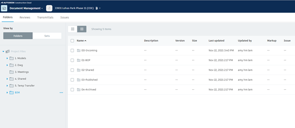
Tất cả các mô hình BIM và tài liệu liên quan đến BIM đều được lưu trong thư mục “BIM” trên CDE:

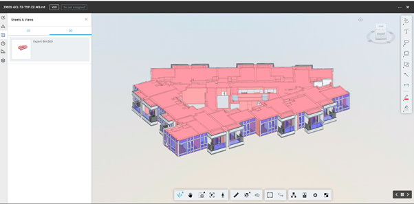
Trình xem mô hình 3D trên BIM360:

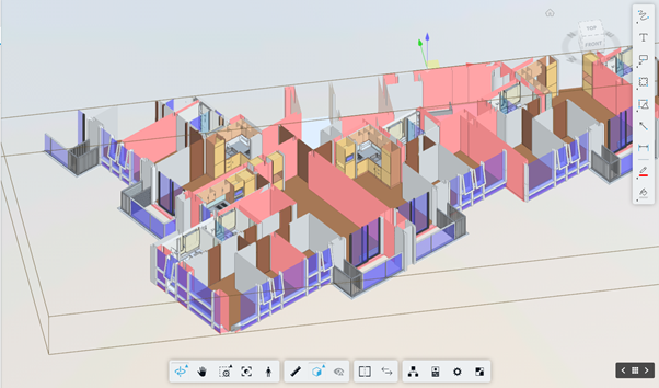
Dễ dàng sử dụng các công cụ như cắt mặt cắt, đo đạc… để xem trực tiếp các mô hình:

3. Tạo các RFI trên BIM360

Yêu cầu cung cấp thông tin (RFI) là một tài liệu được sử dụng trong quá trình thi công nhằm làm rõ các chi tiết cần thiết của một dự án. Trong các dự án xây dựng phức tạp, nhiều RFI được soạn thảo và phản hồi để đảm bảo công việc luôn tiến triển đúng theo thiết kế, thông số kỹ thuật và vật liệu đã quy định.

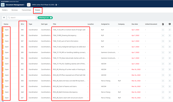
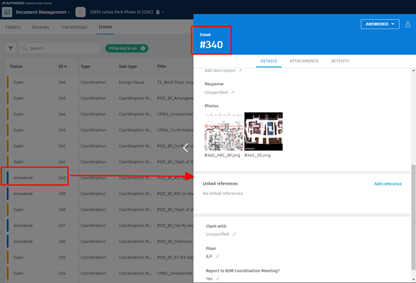
Trong thư mục dự án trên BIM360, người dùng có thể tạo các yêu cầu thông tin (RFI) tại tab “Issues” (các vấn đề). Mỗi RFI được tạo ra sẽ tự động được gán một mã định danh (ID). Người tạo RFI có trách nhiệm nhập đầy đủ thông tin, bao gồm tiêu đề, vị trí tài liệu, ghi chú, hình ảnh… đồng thời chỉ định người nhận và người chịu trách nhiệm xử lý RFI đó. Người được giao nhiệm vụ sẽ phản hồi trực tiếp các vấn đề này cho đến khi RFI được xử lý xong. Sau khi hoàn tất xử lý, trạng thái của RFI sẽ chuyển từ “Open” (Đang mở) sang “Answered” (Đã phản hồi).

Việc theo dõi trực tiếp các yêu cầu thông tin (RFI) trên môi trường dữ liệu chung (CDE) sẽ giúp nhà thầu và chủ đầu tư nhanh chóng nắm bắt các vấn đề phát sinh trong quá trình vận hành BIM xuyên suốt dự án, từ đó giúp việc đưa ra giải pháp trở nên nhanh chóng và khách quan hơn.


Share this:

Phối hợp BIM 3D và cách thức hoạt động

Giới thiệu về điều phối BIM

Ngành xây dựng đã trải qua nhiều lần thay đổi, và những biến chuyển gần đây có lẽ là những thay đổi lớn nhất trong lịch sử. Trước đây, phần lớn quy trình xây dựng đều dựa vào các bản vẽ trên giấy. Sự ra đời của các mô hình 2D trong phần mềm AutoCAD vào thập niên 1960 đã cải thiện tình hình, dù quy trình tổng thể vẫn tiêu tốn nhiều thời gian và còn tồn tại khó khăn trong việc kết nối bản vẽ 2D với các đối tượng thực tế trong không gian 3D.

May mắn thay, vào cuối thập niên 1980, ngành xây dựng đã chứng kiến ​​một bước tiến mới khi các công ty bắt đầu tìm cách áp dụng nhiều công nghệ kỹ thuật số khác nhau (bao gồm cả BIM). Đây chính là khởi đầu của quá trình chuyển đổi số trong ngành xây dựng. Dù phải mất một thời gian khá dài để được chấp nhận và ứng dụng rộng rãi, nhưng hiện nay, BIM đã trở thành công cụ được sử dụng thường xuyên, góp phần giải quyết nhiều vấn đề trong lĩnh vực xây dựng.

Trong ngành xây dựng, khái niệm phát hiện xung đột (clash detection) và phối hợp (coordination) trong BIM thường được xem là có thể thay thế cho nhau. Cả hai đều được coi là yếu tố thiết yếu để đảm bảo thiết kế được hiện thực hóa đúng như mong đợi, mà không phát sinh vấn đề hay trở ngại nào.

Vậy, phối hợp BIM là gì? Nhìn chung, đây là một quy trình trong Mô hình Thông tin Công trình (BIM) giúp thúc đẩy sự phối hợp giữa các phương án thiết kế cơ điện (MEP), kết cấu và kiến ​​trúc.

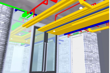
Một trong những mục tiêu chính của công tác điều phối BIM là đạt được hiệu quả cộng tác cao hơn thông qua việc kết hợp nỗ lực từ các bộ môn chuyên môn khác nhau trong một dự án xây dựng cụ thể. Theo đó, việc phát hiện xung đột là một phần thiết yếu trong công tác điều phối BIM 3D, giúp xác định các vấn đề giữa những thiết kế và mô hình khác nhau, từ đó tìm ra phương án tối ưu nhất để khắc phục.

Các xung đột có thể được phân loại thành dạng “nhẹ” (soft) hoặc “nặng” (hard); sự khác biệt chính giữa hai loại này nằm ở mức độ nỗ lực cần thiết để giải quyết một vấn đề cụ thể. Các xung đột dạng nhẹ có thể được xử lý dễ dàng bằng cách điều chỉnh nhỏ mô hình BIM, trong khi những xung đột dạng nặng đòi hỏi một đội ngũ kỹ sư có năng lực cùng phối hợp để giải quyết.

Thông thường, công tác phối hợp BIM liên quan đến các mô hình đa bộ môn – tập hợp các mô hình khác nhau tại cùng một không gian – nhằm hỗ trợ phát hiện các vấn đề trong quá trình thi công. Một số loại mô hình có thể được đưa vào các mô hình đa bộ môn này bao gồm:

  • Mô hình kiến ​​trúc nội thất
  • Mô hình hệ thống cơ khí
  • Mô hình cấu kiện đúc sẵn
  • Mô hình kết cấu
  • Mô hình kiến ​​trúc ngoại thất
  • Mô hình cảnh quan
  • Mô hình hệ thống điện

Những lợi ích của công tác phối hợp BIM

Hai trong số các bên hưởng lợi nhiều nhất từ ​​việc áp dụng quy trình phối hợp BIM vào quá trình xây dựng chính là các kỹ sư và kiến ​​trúc sư. Quy trình phối hợp BIM 3D mang lại nhiều lợi ích khác nhau, bao gồm nhưng không giới hạn ở những điểm sau:

  • Dễ dàng phát hiện các lỗi thiết kế – những lỗi mà nếu để đến giai đoạn cuối của dự án mới tìm ra thì sẽ tốn rất nhiều chi phí để khắc phục.
  • Tối ưu hóa việc sử dụng không gian công trình.
  • Tính năng phát hiện xung đột (clash detection) trong Revit hoặc Navisworks giúp giảm đáng kể số lượng thay đổi phát sinh trong quá trình thi công, vốn có thể xảy ra nếu các xung đột này không được phát hiện sớm.
  • Lập tiến độ thi công theo thời gian thực cũng là một trong những lợi ích mang lại từ quá trình phối hợp BIM 3D.
  • Có thể thực hiện thêm các điều chỉnh hoặc cải tiến thiết kế nhờ vào hệ thống mô hình chi tiết và các báo cáo 3D toàn diện.
  • Việc phối hợp BIM giúp các bên liên quan – bao gồm kỹ sư, kiến ​​trúc sư, nhà thầu, v.v. – cộng tác dễ dàng hơn; từ đó nâng cao độ chính xác cho tổng thể thiết kế và giải quyết các vấn đề trước khi chúng trở nên nghiêm trọng hơn trong tương lai.
  • Nhiều kỹ sư có thể cùng làm việc trên một mô hình thống nhất, trong đó mọi thay đổi từ mỗi cá nhân đều được cập nhật và phản ánh đầy đủ.

Việc phối hợp thông qua BIM mang lại nhiều lợi ích to lớn cho toàn bộ dự án xây dựng; nó giúp cải thiện sự phối hợp giữa các bộ phận và các giai đoạn của dự án, đồng thời hỗ trợ giải quyết các vấn đề về tính tương thích, tình trạng lãng phí quá mức cùng nhiều vấn đề khác.

Quy trình phối hợp BIM

Mặc dù quy trình thực tế có thể khác biệt đáng kể tùy thuộc vào nhiều yếu tố — từ loại hình công trình, phạm vi dự án cho đến các loại vật liệu được sử dụng — vẫn có một số bước chung trong công tác phối hợp BIM mà chúng tôi có thể chia sẻ. Các bước đó bao gồm:

  1. Việc đặt mô hình đúng vị trí là yếu tố cốt yếu. Chỉ cần một sai lệch nhỏ giữa hai mô hình cũng sẽ dẫn đến dữ liệu không chính xác về các vấn đề phát sinh; do đó, độ chính xác là điều vô cùng quan trọng. Quy trình kiểm tra vị trí tương đối giữa các mô hình sẽ khác nhau tùy thuộc vào phần mềm mà bạn sử dụng; chẳng hạn, các phần mềm như Revit cung cấp các tính năng như hệ tọa độ, điểm gốc dự án (project base point) và liên kết mô hình (model linking), cùng nhiều công cụ khác giúp đảm bảo các mô hình được đặt đúng vị trí.
  2. Việc lựa chọn công cụ phối hợp BIM (BIM coordination tools) đóng vai trò rất quan trọng. Thị trường các công cụ này vô cùng rộng lớn và đa dạng, nhưng có thể phân loại thành ba nhóm chính:
    Môi trường dữ liệu chung (Common Data Environments – CDE): Một số nền tảng CDE cho phép thực hiện kiểm tra va chạm giữa các mô hình khác nhau trên cùng một không gian lưu trữ đám mây. Các ví dụ phổ biến bao gồm Autodesk BIM 360, Trimble Connect, v.v.
    Các công cụ mô hình hóa: Đây là lựa chọn phù hợp cho những người thực hiện mô hình hóa cho nhiều bộ môn khác nhau trong cùng một phần mềm; chẳng hạn như Autodesk Revit, vốn cung cấp tính năng kiểm tra va chạm cho các mô hình được liên kết (linked models).
    Các công cụ phối hợp BIM chuyên dụng: Đây là nhóm giải pháp toàn diện nhất về khả năng phát hiện va chạm, thường bao gồm các quy tắc phát hiện, báo cáo phối hợp và nhiều tính năng nâng cao khác. Những ví dụ tiêu biểu trên thị trường là Navisworks Manage và Solibri Office.
  3. Một định dạng chung để các mô hình có thể phối hợp với nhau. Mặc dù đôi khi các chuyên môn khác nhau có thể cùng làm việc trên một phần mềm, nhưng cũng thường xảy ra trường hợp các mô hình được tạo ra từ nhiều phần mềm khác nhau như Revit, ArchiCAD, Tekla, v.v. Việc hợp nhất tất cả các mô hình này sẽ rất khó khăn nếu không có một định dạng chung như IFC (Industry Foundation Classes – một tiêu chuẩn toàn cầu cho phép trao đổi thông tin quản lý công trình giữa các phần mềm khác nhau). Cần lưu ý rằng, tùy thuộc vào phần mềm bạn đang sử dụng, một số thành phần trong mô hình có thể không được chuyển đổi chính xác sang định dạng IFC. Do đó, đây là vấn đề cần được tìm hiểu kỹ lưỡng ngay từ đầu.
  4. Kết hợp các mô hình IFC khác nhau. Nếu bạn đang làm việc với nhiều mô hình khác nhau được xuất sang định dạng IFC, thì việc kết hợp chúng lại với nhau là điều hoàn toàn hợp lý. Thông thường, bạn nên sử dụng các công cụ chuyên dụng cho công tác phối hợp BIM (BIM coordination) để thực hiện việc này, chẳng hạn như Solibri hoặc Navisworks.
  5. Hãy cân nhắc phạm vi của quá trình kiểm tra phối hợp. Sau khi hợp nhất các mô hình khác nhau thành một mô hình duy nhất, đã đến lúc xác định các yêu cầu cụ thể. Bạn chỉ cần kiểm tra xung đột giữa các mô hình, hay còn muốn kiểm tra cả tính nhất quán của thông tin? Bạn có cần kiểm tra xem các thiết bị cơ, điện, nước (MEP) đã được bố trí tuân thủ các tiêu chuẩn liên quan hay chưa? Bạn có cần kiểm tra khoảng cách hợp lý giữa các hệ thống lắp đặt và các cấu kiện xây dựng không? Đây là một số câu hỏi giúp bạn xác định phạm vi kiểm tra. Bước này cũng được xem là điểm khởi đầu cho toàn bộ quy trình phối hợp.
  6. Xác định các quy tắc kiểm tra. Bước này phụ thuộc hoàn toàn vào bước trước đó, chuyển đổi các câu trả lời cho những câu hỏi đó thành các quy tắc cụ thể để phần mềm phối hợp BIM có thể vận hành. Tại bước này, bạn sẽ chọn phạm vi kiểm tra, mức độ chi tiết của quá trình kiểm tra, cùng các yếu tố khác.
  7. Hãy thực hiện kiểm tra mô hình. Nếu phần mềm bạn đang sử dụng không tự động thực hiện việc này, bạn cần khởi chạy quy trình kiểm tra theo cách thủ công. Khi đó, chương trình sẽ dựa trên các quy tắc đã thiết lập trước đó để rà soát toàn bộ mô hình, nhằm phát hiện những điểm không nhất quán hoặc các va chạm. Sau khi quá trình hoàn tất, một danh sách các va chạm được tìm thấy sẽ hiển thị; bạn có thể xem chi tiết từng vấn đề nếu muốn kiểm tra thủ công.
  8. Hãy xác định những người chịu trách nhiệm khắc phục các va chạm mà bạn đã tìm thấy. Một số phần mềm chuyên dụng như Solibri cho phép bạn xem nhãn của bộ phận cần chịu trách nhiệm xử lý từng lỗi va chạm cụ thể. Tuy nhiên, đây chỉ mang tính chất gợi ý; trách nhiệm của điều phối viên BIM là phải xác định xem vấn đề nào có thể được giải quyết bởi một vài cá nhân, và vấn đề nào đòi hỏi sự tham gia của cả một bộ phận.
  9. Trao đổi với các thành viên trong nhóm về việc xử lý các va chạm (xung đột). Đây là bước tiếp nối hợp lý từ giai đoạn trước, tập trung vào việc thông báo cho đúng người hoặc bộ phận liên quan về các vấn đề cần khắc phục. Các báo cáo về va chạm sẽ hỗ trợ đắc lực cho điều phối viên BIM trong việc truyền đạt chính xác phạm vi vấn đề đến các bên liên quan; hầu hết các phần mềm điều phối BIM hiện nay đều có khả năng tạo ra các báo cáo này.
  10. Hãy phân tích kết quả của quá trình xử lý va chạm và xác định các bước tiếp theo cần thực hiện. Việc thu thập thông tin về toàn bộ mô hình sẽ mang lại lợi ích lâu dài, giúp điều phối viên BIM nhận biết liệu một số bộ môn cụ thể trong mô hình có đang gặp nhiều lỗi va chạm hơn các bộ môn khác hay không. Ngoài ra, việc trao đổi kết quả kiểm tra phối hợp BIM với các bộ phận liên quan sẽ góp phần đáng kể vào việc hạn chế sự xuất hiện của các vấn đề này trong tương lai.

Có lẽ bạn đã nhận thấy rằng công tác điều phối BIM nói chung không phải là một quy trình đơn giản; nó đòi hỏi người thực hiện phải có một nền tảng kiến ​​thức lý thuyết nhất định để có thể triển khai một cách chuẩn xác. Tuy nhiên, chúng tôi đã đúc kết được 10 bước phổ biến trong quy trình này, cùng với một số thông tin bổ sung liên quan đến từng bước.

Phần kết luận

Như bạn có thể thấy, điều phối BIM không chỉ đơn thuần là quá trình kiểm tra va chạm tự động, mà còn bao hàm nhiều khía cạnh hơn thế. Chúng ta đã cùng tìm hiểu định nghĩa về điều phối BIM, những lợi ích mà nó mang lại cho dự án, cũng như kế hoạch tổng thể để triển khai điều phối BIM như một quy trình làm việc.

Share this:

Thiết kế phục vụ sản xuất và lắp ráp (DfMA)

Giới thiệu về DfMA

Thiết kế phục vụ sản xuất và lắp ráp (DfMA) là một phương pháp thiết kế chú trọng vào sự thuận tiện trong quá trình sản xuất và tính hiệu quả trong khâu lắp ráp. Bằng cách đơn giản hóa thiết kế sản phẩm, doanh nghiệp có thể thực hiện việc sản xuất và lắp ráp hiệu quả hơn, trong thời gian ngắn nhất và với chi phí thấp hơn.

Theo truyền thống, DfMA (Thiết kế để sản xuất và lắp ráp) đã được áp dụng trong các lĩnh vực như thiết kế ô tô và sản phẩm tiêu dùng – những ngành đòi hỏi khả năng sản xuất hiệu quả các sản phẩm chất lượng cao với số lượng lớn. Gần đây hơn, các nhà thầu xây dựng đã bắt đầu áp dụng DfMA vào việc chế tạo sẵn các cấu kiện xây dựng tại nhà máy (off-site), chẳng hạn như các tấm sàn bê tông, cột và dầm kết cấu, v.v.

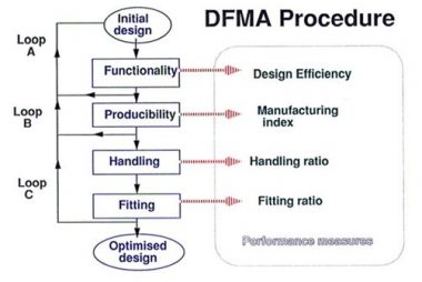
DfMA kết hợp hai phương pháp luận – Thiết kế để sản xuất (DFM) và Thiết kế để lắp ráp (DFA):

Thiết kế để sản xuất (DFM)

DFM (Design for Manufacturing – Thiết kế để sản xuất) bao gồm việc thiết kế các thành phần cấu tạo nên sản phẩm sao cho dễ dàng sản xuất. Phương pháp này tập trung vào việc lựa chọn các loại vật liệu và quy trình sản xuất tối ưu về chi phí, đồng thời giảm thiểu sự phức tạp trong các thao tác sản xuất.

Thiết kế để lắp ráp (DFA)

DFA (Design for Assembly – Thiết kế để lắp ráp) tập trung vào việc thiết kế sản phẩm sao cho dễ lắp ráp. Phương pháp này hướng tới mục tiêu giảm chi phí lắp ráp sản phẩm và tối thiểu hóa số lượng các thao tác lắp ráp.

Cả DFM và DFA đều hướng tới việc giảm chi phí vật liệu, chi phí quản lý và chi phí nhân công.

Các nguyên tắc DfMA

Tương tự như phương pháp xây dựng tinh gọn (lean construction), việc áp dụng DfMA cho phép xác định, định lượng và loại bỏ các yếu tố lãng phí hoặc kém hiệu quả trong quá trình sản xuất và lắp ráp sản phẩm. Phương pháp này cũng có thể được sử dụng như một công cụ đối chuẩn (benchmarking) để nghiên cứu các sản phẩm từ đối thủ cạnh tranh.

Các nguyên tắc chính của DfMA là:

  • Giảm thiểu số lượng linh kiện: Qua đó giúp cắt giảm chi phí lắp ráp và đặt hàng, giảm lượng sản phẩm dở dang, đồng thời đơn giản hóa quá trình tự động hóa.
  • Thiết kế để dễ chế tạo linh kiện: Hình dạng của các linh kiện cần được đơn giản hóa và loại bỏ những chi tiết không cần thiết.
  • Dung sai linh kiện: Các linh kiện cần được thiết kế sao cho nằm trong phạm vi năng lực của quy trình sản xuất.
  • Tính rõ ràng: Các linh kiện nên được thiết kế sao cho chỉ có thể lắp ráp theo một cách duy nhất.
  • Hạn chế sử dụng các linh kiện linh hoạt: Nên hạn chế các chi tiết làm bằng cao su, gioăng, cáp, v.v., vì việc xử lý và lắp ráp chúng thường khó khăn hơn.
  • Thiết kế để dễ lắp ráp: Chẳng hạn, ưu tiên sử dụng các khớp nối nhanh (snap-fit) hoặc chất kết dính thay vì các loại ốc vít, bu-lông. Nếu có thể, sản phẩm nên được thiết kế với một linh kiện nền tảng để định vị các linh kiện khác một cách nhanh chóng và chính xác.
  • Loại bỏ hoặc giảm thiểu các thao tác điều chỉnh: Việc thiết kế các chi tiết cần điều chỉnh sẽ làm tăng nguy cơ xảy ra tình trạng sai lệch thông số kỹ thuật trong quá trình sử dụng.

Các ưu điểm của DfMA

Một số ưu điểm chính của DfMA bao gồm:

Tốc độ
Một trong những ưu điểm chính của phương pháp DfMA trong xây dựng là giúp giảm đáng kể tiến độ thi công tại công trường nhờ việc sử dụng các cấu kiện được chế tạo sẵn.

Giảm chi phí lắp ráp

Bằng cách sử dụng ít linh kiện hơn, giảm bớt khối lượng công việc cần thực hiện và cắt giảm số lượng các loại linh kiện khác nhau, DfMA có thể giúp giảm đáng kể chi phí lắp ráp.

Chất lượng cao hơn và tính bền vững

Phương pháp tự động hóa cao có thể nâng cao chất lượng và hiệu quả ở từng giai đoạn.
Cách tiếp cận này có thể giúp giảm thiểu lượng chất thải phát sinh trong giai đoạn thi công, tăng hiệu quả trong công tác hậu cần tại công trường, đồng thời giảm bớt số lượt phương tiện vận chuyển vật liệu đến công trường.

Thời gian lắp ráp ngắn hơn
DFMA rút ngắn thời gian lắp ráp bằng cách tận dụng các phương pháp lắp ráp tiêu chuẩn, chẳng hạn như lắp ráp theo phương thẳng đứng và sử dụng các chi tiết có khả năng tự căn chỉnh. DFMA cũng đảm bảo quá trình chuyển tiếp từ giai đoạn thiết kế sang giai đoạn sản xuất diễn ra một cách suôn sẻ và nhanh chóng nhất có thể.

Độ tin cậy cao hơn

DfMA giúp tăng độ tin cậy bằng cách giảm số lượng linh kiện, từ đó làm giảm nguy cơ xảy ra lỗi.

Độ an toàn
Việc đưa các hoạt động thi công ra khỏi công trường và chuyển vào môi trường nhà máy được kiểm soát có thể tạo ra tác động tích cực đáng kể đối với vấn đề an toàn.

Share this:

CSD và CBWD

CSD và CBWD là gì?

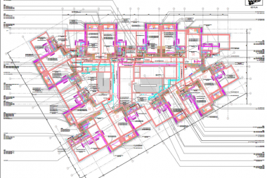
CSD (Combined Services Drawing – Bản vẽ phối hợp hệ thống) là bản vẽ tích hợp các hệ thống kỹ thuật trong các dự án xây dựng. Bản vẽ này bao gồm mặt bằng và mặt cắt của các phòng, không gian và tầng nhà, thể hiện rõ ràng, chi tiết kích thước cũng như vị trí của tất cả các thành phần thuộc các hệ thống cơ, điện, nước (MEP).
CBWD (Combined Builders Work Drawing – Bản vẽ phối hợp công tác xây dựng) là bản vẽ tổng hợp các yêu cầu về kết cấu/kiến trúc phục vụ cho việc lắp đặt hệ thống kỹ thuật; bản vẽ này thể hiện chi tiết vị trí các lỗ mở hoặc khoảng trống cần tạo ra trên các cấu kiện xây dựng (như tường, dầm, sàn, cột) do sự giao cắt với các thành phần của hệ thống MEP.

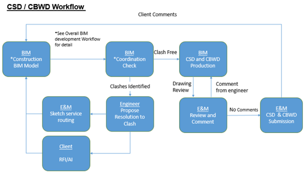
Process of creating CSD & CBWD drawings

Mục đích của CSD & CBWD

Các bản vẽ CSD được các nhà thầu thi công sử dụng để theo dõi và xác định nguyên lý vận hành cũng như hướng bố trí của các hệ thống cơ điện (MEP) trong công trình. Từ đó, họ có thể lập kế hoạch điều chỉnh các bản vẽ thiết bị sao cho tối ưu hóa hoạt động của các bộ phận, đồng thời tiết kiệm chi phí ở mức tối đa.

Các bản vẽ CBWD được các nhà thầu thi công sử dụng để theo dõi và xác định vị trí, kích thước cũng như cao độ của các lỗ mở chờ sẵn trên các cấu kiện kiến ​​trúc và kết cấu. Loại bản vẽ này có thể được chuyển trực tiếp đến bộ phận thi công, giúp nhà thầu xây dựng kế hoạch thi công hợp lý và chính xác, từ đó giảm thiểu các vấn đề phát sinh cũng như chi phí khắc phục sai sót về sau.

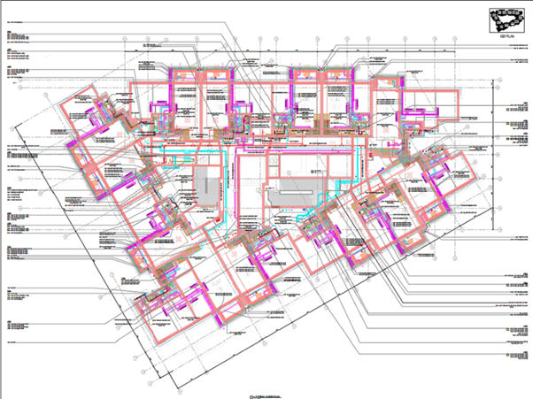
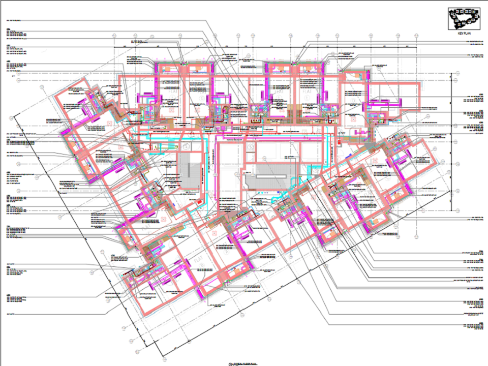
Sơ đồ mặt bằng CSD điển hình
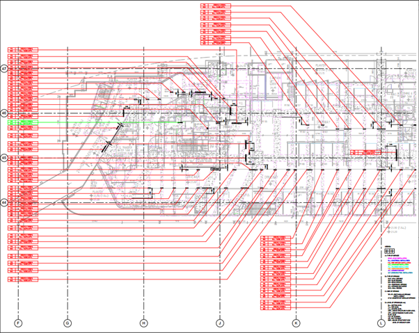
Sơ đồ điển hình của CBWD

Quy trình thực hiện bản vẽ CSD và CBWD

Sau khi kết hợp các mô hình từ tất cả các bộ môn – bao gồm kiến ​​trúc, kết cấu và cơ điện (MEP) – thành một mô hình thống nhất gọi là Mô hình BIM (Mô hình BIM tổng hợp), kỹ sư sẽ tiến hành quy trình phát hiện và giải quyết các xung đột. Mô hình cuối cùng, sau khi đã xử lý triệt để các xung đột, sẽ được sử dụng để xuất ra các bản vẽ CSD (Bản vẽ phối hợp thi công) và CBWD (Bản vẽ chi tiết lỗ mở thi công).

Các kỹ sư sẽ thiết lập những góc nhìn (view) cần thiết cho từng bộ môn – bao gồm mặt bằng, mặt cắt và mặt đứng – ngay trong mô hình BIM chuyên biệt của bộ môn đó, nhằm chuẩn bị cho công tác phối hợp với các bộ môn khác. Tiếp đó, kỹ sư thực hiện ghi kích thước, chú thích chi tiết các cấu kiện trên những góc nhìn này rồi đưa chúng vào các khung bản vẽ. Dưới đây là một số góc nhìn điển hình trong một bản vẽ CSD.

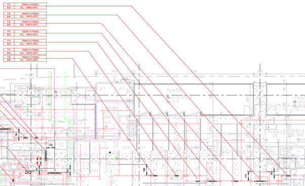
Đối với bản vẽ CBWD, các kỹ sư cũng tạo ra các góc nhìn tương tự, bao gồm mặt bằng, mặt đứng và mặt cắt tại các vị trí có lỗ mở; đồng thời bổ sung kích thước, nhãn chú thích để làm rõ vị trí, kích thước và cao độ của các lỗ mở đó. Các lỗ mở thi công liên quan đến hệ thống của bộ môn nào sẽ được hiển thị trong các góc nhìn riêng của bộ môn đó và ẩn đi đối với các bộ môn còn lại, giúp đơn vị thi công dễ dàng theo dõi và hình dung vị trí các lỗ mở hơn. Hình ảnh dưới đây là một mặt bằng CBWD điển hình.

Dimensions and tags details in CBWD drawing
Share this:
Contact Me on Zalo
Call now