Design for Manufacture and Assembly (DfMA)
DfMA Introduction
Design for Manufacture and Assembly (DfMA) is a design approach that focuses on ease of manufacture and efficiency of assembly. By simplifying the design of a product it is possible to manufacture and assemble it more efficiently, in the minimum time and at a lower cost.
Traditionally, DfMA has been applied to sectors such as the design of automotive and consumer products, both of which need to efficiently produce high quality products in large numbers. More recently, construction contractors have begun to adopt DfMA for the off-site prefabrication of construction components such as concrete floor slabs, structural columns and beams, and so on.
DfMA combines two methodologies – Design for Manufacture (DFM) and Design for Assembly (DFA):
Design for Manufacture (DFM)
DFM involves designing for the ease of manufacture of a product’s constituent parts. It is concerned with selecting the most cost-effective materials and processes to be used in production, and minimizing the complexity of the manufacturing operations.
Design for Assembly (DFA)
DFA involves design for a product’s ease of assembly. It is concerned with reducing the product assembly cost and minimizing the number of assembly operations.
Both DFM and DFA seek to reduce material, overhead, and labor costs.
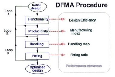
DfMA Principles
In a similar approach to lean construction, applying DfMA enables the identification, quantification and elimination of waste or inefficiency in product manufacture and assembly. It can also be used as a benchmarking tool to study the products of competitors.
The main principles of DfMA are:

- Minimise the number of components: Thereby reducing assembly and ordering costs, reducing work-in-process, and simplifying automation.
- Design for ease of part-fabrication: The geometry of parts is simplified and unnecessary features are avoided.
- Tolerances of parts: Part should be designed to be within process capability.
- Clarity: Components should be designed so they can only be assembled one way.
- Minimise the use of flexible components: Parts made of rubber, gaskets, cables and so on, should be limited as handling and assembly is generally more difficult.
- Design for ease of assembly: For example, the use of snap-fits and adhesive bonding rather than threaded fasteners such as nuts and bolts. Where possible a product should be designed with a base component for locating other components quickly and accurately.
- Eliminate or reduce required adjustments: Designing adjustments into a product means there are more opportunities for out-of-adjustment conditions to arise.
Advantages of DfMA
Some of the main advantages of DfMA include:
Speed
One of the primary advantages of DfMA in construction is the significantly reduced programmed on-site through the use of prefabricated elements.
Lower assembly cost
By using fewer parts, decreasing the amount of labor required, and reducing the number of unique parts, DfMA can significantly lower the cost of assembly.
Higher quality and sustainability
A highly automated approach can enhance quality and efficiency at each stage.
There may be less waste generation in the construction phase, greater efficiency in site logistics, and a reduction in vehicle movements transporting materials to site.
Shorter assembly time
DFMA shortens assembly time by utilising standard assembly practices such as vertical assembly and self-aligning parts. DFMA also ensures that the transition from the design phase to the production phase is as smooth and rapid as possible.
Increased reliability
DfMA increases reliability by lowering the number of parts, thereby decreasing the chance of failure.
Safety
By removing construction activities from the site and placing them in a controlled factory environment there is the possibility of a significant positive impact on safety.
