Introduction to BIM Coordination
The construction industry has evolved multiple times, and recent changes might be the biggest ones in history. Historically, most of the construction process relied on paper drawings. The introduction of 2D models in AutoCAD in the 1960s helped matters since the entire process still took a lot of time, but still had problems connecting the 2D drawing with the 3D real-world object.
Luckily enough, the late 1980s saw another evolution of the construction industry, with companies looking into adopting various digital technologies (including BIM). This is how digital transformation began in the construction industry. Unfortunately, it took BIM a while to become widely accepted and adopted, but now it is used on a regular basis and helps with solving many construction problems.
Both BIM clash detection and BIM coordination are mostly interchangeable in the construction industry. Both of them are considered essential for a design to be realized as expected, with no problems or issues.
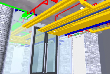
So, what is BIM coordination? In general, it is a process of Building Information Modeling that facilitates the collaboration between MEP engineering, structural engineering and architectural plans.
One of the main goals of BIM coordination is to reach more efficient collaboration results by combining the efforts of different disciplines within a particular construction project. As such, clash detection is an essential part of 3D BIM coordination that can locate issues between different designs and models to work out the most efficient way to fix them.
Clashes themselves could be either soft or hard, and the main differences between the two is the amount of effort needed to solve a particular case. Soft cases can easily be resolved by slightly changing the BIM Model, while some of the harder cases would require a team of competent engineers to work through and resolve.
More often than not, BIM coordination deals with multidisciplinary models, which are the collection of the different models in one place, helping to look for the construction issues. Some of the model types that can be included in the multidisciplinary models are:
- Interior architectural model
- Mechanical services model
- Prefabrication model
- Structural model
- Exterior architectural model
- Landscape model
- Electrical services model
The benefits of BIM coordination
Two of the main parties that are heavily benefitting from the introduction of BIM coordination into the construction process are engineers and architects. There are several different benefits that 3D BIM coordination provides, including, but not exclusive to:
- Easier location of design errors that would cost a lot of money to fix in the final project state.
- Maximized utilization of the building space.
- Clash detection within Revit of Navisworks is capable of greatly reducing the number of changes that would’ve happened in the construction process if the clashes were not detected sooner.
- Real time construction scheduling is also one of the byproducts of 3D BIM coordination.
- Additional design modifications and/or improvements are possible thanks to the detailed mapping and extensive 3D reports.
- BIM coordination makes it easier to collaborate between different departments such as engineers, architects, contractors, and so on – improving the accuracy of the design as a whole and resolving issues before they’ve become much bigger down the road.
- Multiple engineers can work on a unified model that would reflect changes from each and every one of them.
BIM coordination offers a great variety of benefits for the construction project as a whole, improving coordination between departments and stages of the project, helping with compatibility issues, excessive waste issues, and many others.
The process of BIM Coordination
While the process itself may differ greatly depending on various factors, from the construction type to the scope and the materials used, there are some general steps of BIM coordination that we can share. These steps are:
- Correct model placement is essential. Even a slight margin of error between two models would result in incorrect data about the issues, which is why the accuracy is crucial. The process of checking for the model placement in relation to each other is different depending on the software that you’re using, but something like Revit offers you coordinates, project base point and model linking, among other things that help with the correct model placement.
- The importance of choosing between BIM coordination tools. The market for these tools is vast and varied, but it’s possible to discern three main groups of BIM coordination tools:
CDEs, or Common Data Environments. Some participants of the CDE market allow for collision checks between different models within the same cloud, with the popular examples in the form of Autodesk BIM 360, Trimble Connect and so on.
Modeling tools. A suitable option for someone who’s modeling different disciplines with one tool, since some of them (like Autodesk Revit) offer collision checks for linked models.
BIM coordination tools. The most extensive option when it comes to information about collision detection, often includes detection rules, coordination reports, and many other features. Some of the best examples of the market are Navisworks Manage and Solibri Office. - A common format for models to work with. While there are some cases of different disciplines working within the same software, there are also a lot of cases when you have several different models from different software pieces, such as Revit, ArchiCAD, Tekla, or others. Merging all of these models in one might be problematic if it weren’t for a common format such as IFC (Industry Foundation Classes, it is a global standard for building management information to work with across different software appliances). It’s important to keep in mind that some parts of your model might not be converted into the IFC format correctly depending on the software you’re using. This is why it’s a topic that requires further investigation beforehand.
- Combining different IFC models. If we’re continuing with several different models being exported in IFC format, it’s only a common sense for you to combine them. Most of the time it’s recommended to use one of the BIM coordination-specific tools for this purpose, such as Solibri or Navisworks.
- Think about the scope of the coordination check. After merging different models into a single one, it’s time to assess the extent of your requirements. Do you need to only check for collisions between models, or you also want to check for the information consistency, as well? Do you need to check if your MEP appliances are placed in accordance with all of the relevant standards? Do you need to check for an appropriate distance between installations and construction elements? These are some of the questions that might help you figure out the scope of your checking. This is also considered to be the beginning of the coordination process as a whole.
- Determine the checking rules. This step depends entirely on the previous one, turning the answers to those questions into specific rules for the BIM coordination software to work with. At this step you’re choosing the scope of your check, its thoroughness, and more.
- Perform a model check. If your software in question does not perform the check automatically, this is where you’re initiating it manually, so that the program can use your previously set rules to check the entire model for inconsistencies and collisions. After the process is complete, you’ll be presented with a list of collisions that were found, and you should have the ability to see each of the problems individually if you want to check them manually.
- Figure out the people responsible for fixing collisions you’ve found. Some specific software like Solibri allows you to see the label of the department that should be responsible for fixing each of your specific collision errors. However, it is still a suggestion more than anything else, and it is a responsibility of a BIM coordinator to figure out which problem can be fixed by only a few people and what needs an entire department’s worth of workforce.
- Communicate with team members on the topic of fixing the collisions. A logical continuation of the previous step, in this one it’s all about notifying the correct people or departments about the problems that need fixing. Collision reports would go a long way in helping a BIM coordinator with communicating the correct extent of the problem with other people, and most of the BIM coordination software should be capable of generating those reports.
- Analyze the results of collision fixing and figure out your next steps. Collecting information about the entire model is helpful in the long run, as well, allowing for a BIM coordinator to figure out if some specific disciplines of the model are having more collision errors than the others. Communicating the results of your BIM coordination check with different departments would go a long way in helping these problems to appear less in the future.
You may have noticed that BIM coordination as a whole is not an easy process and it requires at least some of the theoretical knowledge before attempting to do it correctly. However, we’ve managed to figure out 10 common steps in this process, as well as some additional information about them.
Conclusion
As you can see, BIM coordination as a process is not just automated collision checking, it is much more than that. We went over the definition of BIM coordination, as well as its benefits for the project and the general plan of working with BIM coordination as a process.


